Introduction
EMMUA 214 STATES: Page 35
Installation
4.1 Working Essentials
The following information is considered essential knowledge prior to working in a potentially explosive atmosphere:
4.1.1 Competency
Technicians need proven competence to undertake work in potentially explosive atmospheres. One way to demonstrate basic competence is by the possession of a current CompEx@ Certificate in the appropriate module(s).
Note: Attainment of the CompEx@ (core competency) certificate does not grant to personnel a sufficient level of competency to enable them to work immediately without supervision in potentially explosive atmospheres. Full competency can only come after periods working in such situations under close supervision and after the employer’s responsible person has determined their suitability.
4.1.2 Permits
A ‘Permit to Work’ is required prior to carrying out any work; the terminology used will vary depending on the system used.
4.1.3 Safe Isolation
Recognised procedures are to be followed to ensure that equipment to be worked on is not ‘live’. Exceptions to this may be where only intrinsically safe circuits are involved. In such cases, instruments/meters approved for such an operation must be used.
4.1.4 Tools
Ali tools are to be in sound condition, free from defects and suitable for use in potentially explosive atmospheres. The judgement as to the suitability of tools and instruments may require formal risk assessment.
4.1.5 Personal Equipment
Matches or other forms of ignition are prohibited from being carried into a potentially explosive atmosphere, except in exceptional circumstances where their use is covered by a ‘fire permit’. Items of personal equipment which are battery or solar operated normally worn or carried by personnel can be inadvertently taken into a hazardous area. A basic electronic wrist watch is an example of a low voltage, electronic device which has been independently evaluated and found to be acceptable for use in a hazardous area under both historic and current EPL requirements.
All other personal battery or solar operated equipment (including electronic wrist watches incorporating other devices) shall: conform to a recognised type of protection appropriate to EPL, gas/dust group and temperature class requirements, or
be subjected to a risk assessment, or
c) be taken into the hazardous area under a safe work procedure.
4.2 Terminating in enclosures
4.2.1 Terminating - General
Crimped terminations are required for multi-stranded, particularly fine-stranded, conductors to reduce the risk of stray strands causing circuit faults. Crimped connections are also more readily inserted and removed. Crimping tools of the hand ratchet type (hydraulic in large sizes) are to be used. The simple plier type hand tool often results in joint inconsistency.
Regarding cores per terminal, a good general rule to follow is ‘only one wire per terminal’. Special conditions or types of terminal may sometimes apply and the manufacturer’s documentation may need to be referred to.
For provision for re-terminating cables, sufficient length of conductor core, particularly where multi-core cables are used, should be left to allow for at least one re-termination.
Note: Small terminal boxes may have inadequate room inside to leave spare cable. In these cases, particularly where instrumentation cables are affected, it is preferable to make an external loop (sometimes referred to as a helix) in the cable adjacent to the box.
4.2.2 Unused cores
Unused cores are not to be left un-terminated. Where the equipment has not been provided with sufficient terminals to individually terminate and insulate all unused cores, additional terminals are required. The possibility of adding additional terminals into a certified terminal box should be checked with the manufacturer, or it may be included in the box details. Insulation by tape alone is not permitted.
4.3 Intrinsically safe cabling
Cables in both hazardous and non-hazardous areas shall be installed so as to ensure that intrinsically safe circuit cables cannot be inadvertently connected to circuit cables which are not intrinsically safe. This may be achieved by:
a) separating the different types of circuit cables; or
b) placing the cables so as to protect against the risk of mechanical damage; or
c) using cables which are armoured, metal sheathed or screened for specific types of circuits (e.g. all circuits which are not intrinsically safe are run in armoured cable or all intrinsically safe circuits are armoured).
4.4 Special requirements
4.4.1 Special requirement: Ex’d’ - Flameproof
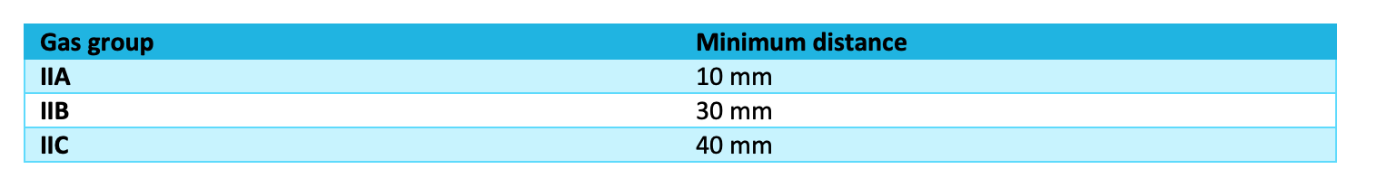
i) Minimum Distance: Gap to an Obstruction
Table 11: Minimum distance of obstruction from the flameproof flange joints related to the gas group of the hazardous area
ii) Use of thread adapters and blanking plugs
No more than one threaded adapter shall be used with a cable gland. The adapter shall be flameproof complying with IEC 60079-1.
Unused cable entries shall be sealed with a flameproof blanking element complying with IEC 60079-1 which shall be fitted directly to the hole (no threaded adapter shall be used) and shall be secured against loosening.
iii) Gaskets
Where gaskets are incorporated in the design, they shall be metallic or made from a non-flammable compressed material contained in a metallic sheath. Removal of the gaskets or changing them for home-made gaskets would invalidate the certificate.
Use of Paint
Seals and gaps should never be painted over indiscriminately. Once fully assembled, it is permitted to paint the enclosure however aluminium paint should never be used. Any paint particles left in a gap after breaking and remaking may result in an excessive gap; the use of non-setting grease will reduce this risk.
use of Grease
Gaps can be protected by the application of a non-hardening grease to flange faces prior to tightening down. Silicone based greases are suitable but should not be used on seats of gas detector heads. Grease may also be used to protect exposed screw threads from corrosion and thereby facilitate their easier removal.
Use of Tape and O-rings
Non-hardening grease-bearing textile tape may be employed on the outside of a straight flanged joint with the following conditions.
-
where the enclosure is used in conjunction with gases allocated to group IIA, the tape should be restricted to one layer surrounding all parts of the flange joint with a short overlap. New tape should be applied whenever existing tape is disturbed;
-
where the enclosure is used in conjunction with gases allocated to Group IIB, the gap between the joint surfaces should not exceed 0.1 mm, irrespective of the flange width. The tape should be restricted to one layer surrounding all parts of the flange joint with a short overlap. New tape should be applied whenever existing tape is disturbed;
-
where the enclosure is used in conjunction with gases allocated to Group IIC, tape should not be applied.
The manufacturer may provide gaskets or O-rings for weatherproofing purposes, both are permissible provided that removing them does not impair the flameproof properties.
Removable Cover Fastenings
All cover fixing bolts need to be fitted and fastened down spanner tight at all times whenever the equipment could possibly be live, even during live testing. Fixing bolt holes are not to be drilled out or break through into the enclosure,
Modifications to Flameproof Equipment
Certified equipment may not be modified in any way, other than as indicated on the certificate. Doing so may invalidate the certificate or produce dangerous operating conditions.
Unauthorised modifications or changes include:
- use of wrong size or type of hole sealing plug;
- use of wrong type of cable entry gland;
- use of any constructional screw for any purpose other than that originally intended;
- attaching cable brackets using cover fixing bolts;
- drilling additional holes in any part of certified Ex ‘d’ equipment for whatever purpose;
- use of any gasket other than specified;
- use of hardening sealants; and changing layout of components in enclosure or adding additional items not included in the Ex ‘d ‘certificate.
4.4.2 Special requirement: Ex’e’ and Ex’n’
i) Terminations into Ex’e’ or Ex’n’ enclosures
Terminals, such as slot types, may receive and clamp more than one conductor. Unless permitted by the certification, two wires of different cross sections should not be connected into one terminal unless first secured within a single compression type ferrule.
Single conductors in single screw type saddle clamps should have the end I-I-shaped around the screw to permit proper clamping. Cable insulation should be maintained right up to the metal of the terminal.